

OPTICAL FIBER LIFECYCLE · 2 NOVEMBER 2026
Fiber slack loops and service reserve: a field acceptance worksheet
Extra cable becomes useful restoration reserve only when its length, location, bend diameter, route and access are controlled. This worksheet helps builders, LCOs, MSOs and facilities teams accept slack storage that can actually support future splicing and repair.
Visual reference photographs
1. Define why reserve is being kept
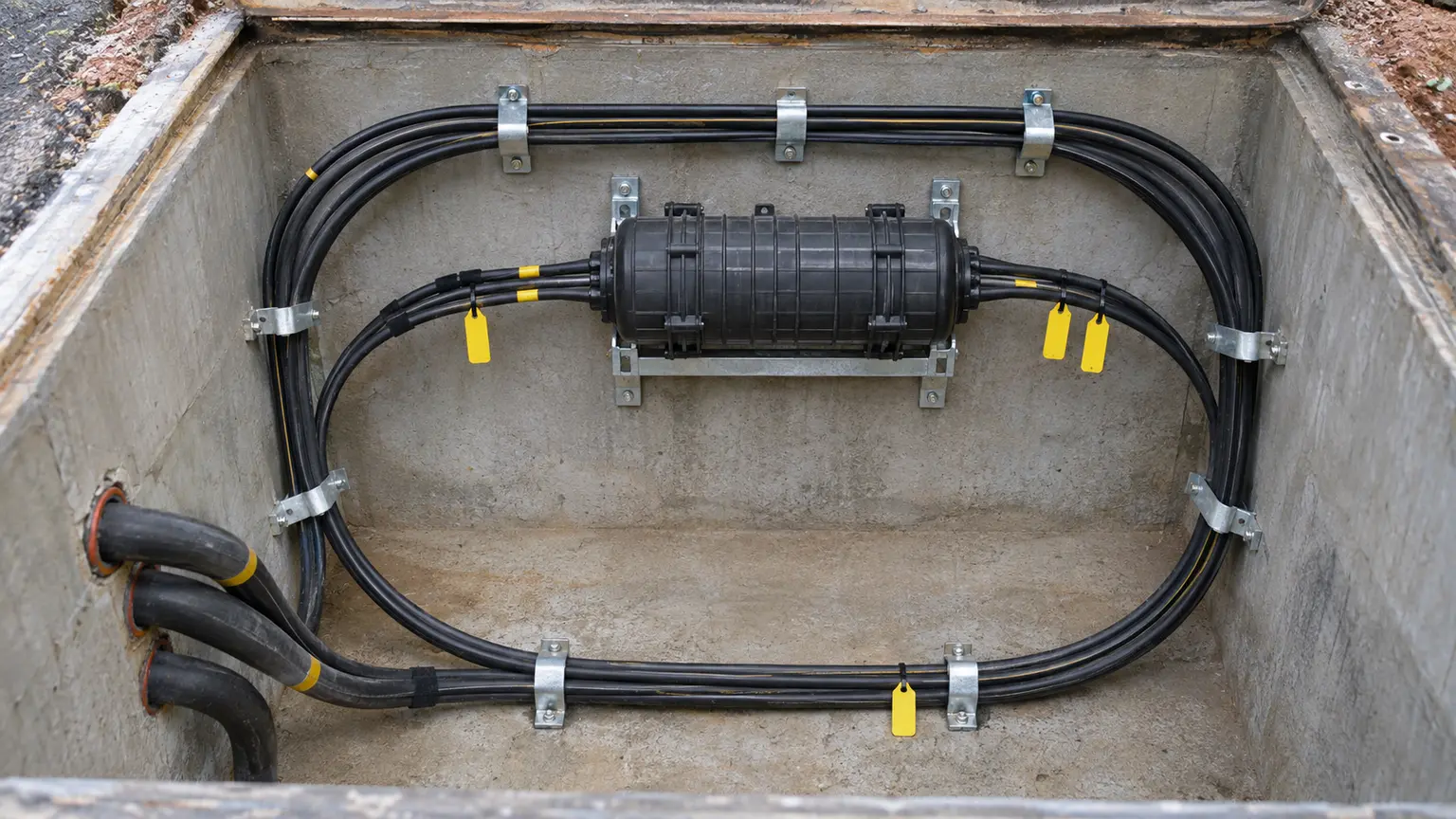
Slack may serve several purposes: reaching a splicing vehicle, moving a closure out of a handhole, replacing a damaged end, relocating a rack, completing a future mid-span access or restoring cable after excavation damage. These purposes require different lengths and access conditions.
For each planned reserve, record the cable ID, route section, location, purpose, measured length, cable construction, outside diameter, minimum installed bend diameter and responsible owner. Corning advises planning slack at termination points to reach the termination or splicing table and allow future repair or equipment movement. FOA similarly notes that service loops must support splicing work and future moves, adds and changes.
2. Calculate usable reserve, not installed reserve
Installed stored length - access lead - damaged section allowance - preparation and closure-entry allowance - inaccessible or prohibited length
Reserve utilization ratio
Usable restoration reserve ÷ installed stored length × 100
Post-repair remaining reserve
Original usable reserve - cable consumed during repair
Define every allowance for the actual site. A splice location beside a vehicle-accessible road differs from a basement shaft or rooftop. Do not publish a universal slack length in the design without checking the route, closure type, cable preparation procedure and access method.
3. Verify bend diameter from the actual cable data
The cable specification, not a generic fiber rule, governs minimum bend radius. Distinguish the installation value under tension from the stored value after installation. Corning requires verification of the minimum bend diameter before arranging vault slack and warns that all stored bends must meet the installed-cable limit.
2 × specified minimum installed bend radius
Measured bend margin
Smallest measured loop diameter - specified minimum loop diameter
Accept only a positive margin that remains after ties, covers and neighbouring cables are installed.
Measure the tightest point, including the cable entry, back of a bracket and crossing between loops. A large-looking coil can still contain one damaging local kink.
4. Select a storage method by environment
| Location | Preferred controls | Common failure |
|---|---|---|
| Handhole or vault | Perimeter routing, radius brackets, closure access, duct clearance and drainage | Intertwined loops, blocked ducts, standing water or crushed cable |
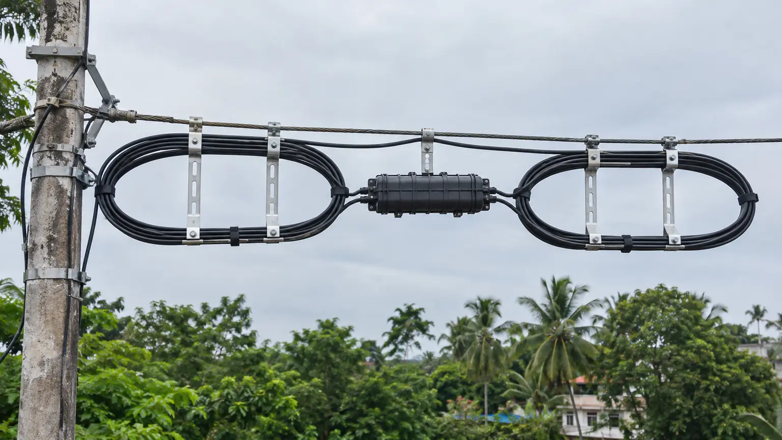
| Aerial messenger | Correct-size snowshoes, secure lashing, separation from pole and protected closure | Tight coil on pole, hanging loop or wind loading |
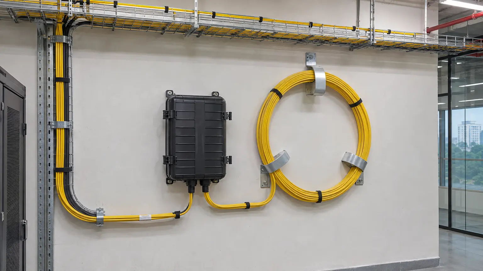
| Telecom room | Wall or rack supports, pathway protection, labeling and fire-stopping continuity | Loose coil behind rack, pinch points or accidental removal |
| Shaft or riser | Rated supports, controlled vertical load and protected access | Reserve weight hanging from termination hardware |
| Cabinet or pedestal | Manufacturer slack basket, segregation and door clearance | Cable trapped by door or mixed with patch cords |
5. Keep slack usable during installation
When long cable must be back-fed, use a controlled figure-eight on a clean groundsheet rather than a circular coil that introduces twist. Corning instructs installers to figure-eight slack where it cannot be damaged by personnel or traffic and to flip it correctly before the next pull. Maintain pulling radius, monitor tension and avoid releasing or reapplying load without coordination.
At intermediate chambers, pull sufficient racking slack from the planned endpoints. Do not drag reserve across concrete, allow vehicles over it or leave the cable unguarded. Record any sheath damage, excessive pull, kink or crush event before the cable is hidden.
6. Protect access, ducts and other cables
Stored slack must not block a duct, sump, manhole step, lifting point, closure fastener or safe working area. Keep cables grouped by route or closure and prevent one service loop from becoming intertwined with another. Use reusable supports that hold the cable without compressing the sheath. FOA warns against over-tightened ties and recommends clear identification to prevent a live cable being mistaken for abandoned cable.
Seal occupied ducts using the specified system and preserve spare-duct access. Where water, rodents, traffic loading or unauthorized access is possible, verify the enclosure, cover and fixing method.
7. Label reserve for restoration
Attach durable labels at both cable entries and the stored loop. Include cable ID, near and far endpoints, fiber count, owner, route direction, closure or ODF reference, approximate reserve length, date and warning status. Do not place labels where they force a tight bend or interfere with sealing.
The as-built drawing should show the slack location and estimated route chainage. The fiber core matrix should reference the same cable ID. Photograph the completed loop with a visible location marker, but do not expose sensitive network details in public records.
8. Measure reserve without damaging it
Use cable jacket meter marks when reliable, installation records or a controlled length measurement. Do not repeatedly uncoil installed reserve only to measure it. Where a loop follows the vault perimeter, record the routing path and number of turns.
Number of complete loops × π × measured mean loop diameter
+ straight entry and exit sections
This is an estimate. Confirm against jacket markings or installation records and state the method and uncertainty.
9. Acceptance tests
- Confirm cable and location against the approved route drawing.
- Verify reserve purpose and required usable length.
- Read the manufacturer bend-radius data for the exact cable.
- Measure the smallest loop diameter and local bends.
- Check entry, exit and bracket contact points.
- Confirm the closure can be moved to the intended work position.
- Verify ducts, sump, steps and safe access remain clear.
- Check ties and supports do not compress the sheath.
- Confirm loops are not intertwined with unrelated cables.
- Inspect for kinks, abrasion, flattening and sheath damage.
- Verify aerial brackets, lashing and pole separation.
- Verify indoor pathway, fire-stopping and rack clearance.
- Check durable labels at each entry and loop.
- Reconcile jacket marks, measured length and as-built record.
- Confirm the remaining reserve after a planned repair scenario.
- Capture photographs and measured values.
- Record deviations and corrective work.
- Assign maintenance ownership and reinspection triggers.
10. Maintenance and restoration controls
Reinspect after chamber flooding, civil work, pole replacement, rack movement, closure re-entry or cable repair. Record how much reserve was consumed and restore the loop geometry. A repair that leaves the cable below minimum bend diameter or removes all future working length is incomplete.
During restoration, verify service before and after movement, control open connectors, preserve fiber identification and update OTDR baselines, route drawings and closure records. Never cut an unidentified loop because it appears unused.
11. Handover worksheet
| Field | Required record |
|---|---|
| Identity | Cable ID, endpoints, route, owner and location |
| Purpose | Splicing access, repair, relocation or future branch |
| Length | Installed, usable and post-repair reserve with method |
| Geometry | Cable OD, bend-radius limit, minimum measured diameter and margin |
| Storage | Supports, lashing, enclosure, drainage, access and duct clearance |
| Condition | Sheath, kinks, crushing, ties, labels and photographs |
| Documents | As-built drawing, closure record, core matrix and maintenance owner |
Primary technical references
- Corning: Installation of preconnectorized cable assemblies
- Corning: Mid-span slack storage in a vault
- Corning: Aerial slack loops and splice closures
- Corning: Duct installation of fiber optic cable
- Fiber Optic Association: Fiber optic installation
- Fiber Optic Association: Fiber optic splice closures
Planning fiber reserve for restoration?
Share the cable type, route, closure locations, rack layout and restoration access requirements. Cyber FTTH Mart can help define reserve quantities, storage geometry, labels and handover records.
Discuss fiber lifecycle acceptance ↗