
ENTERPRISE VOICE NETWORKS · 4 NOVEMBER 2026
LLDP-MED voice VLAN and PoE: a commissioning worksheet
An IP phone that lights up and registers is not proof that the access port is correctly commissioned. The phone may be using the data VLAN, trusting a local setting, receiving the wrong QoS policy or consuming an unsafe power allocation. This worksheet proves the complete LLDP-MED policy path from switch advertisement to endpoint behavior.
Visual reference photographs
1. What LLDP-MED adds to an access port
LLDP-MED extends ordinary Link Layer Discovery Protocol for media endpoints such as IP phones. A network-policy TLV can advertise the voice application, VLAN ID, tagged or untagged behavior, IEEE 802.1p priority and DSCP value. Other MED TLVs can carry capabilities, power and location information. Inventory details may help operations identify phone hardware and firmware.
Cisco, Aruba and Juniper describe the same broad functions, but their defaults and command behavior differ. Some switches wait until a connected endpoint advertises MED capability before sending MED TLVs. A policy may exist globally yet not be attached to the physical port. Power via MDI information may also follow a different precedence from the MED power TLV. Commission against the exact platform and software release, not a copied command set.
2. Define the intended phone and PC traffic model
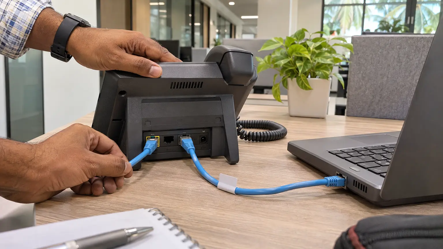
A common desk topology uses one switch port, an IP phone and a computer connected through the phone. Voice frames are normally tagged into a dedicated voice VLAN while PC traffic remains untagged in the access VLAN. The phone must learn the policy, apply the voice tag, preserve the data path and avoid bridging the two security zones.
| Element | Design record | Acceptance evidence |
|---|---|---|
| Data service | Access or native VLAN, authentication and endpoint controls | PC address, gateway, DNS and permitted application test |
| Voice service | Voice VLAN, tagging, PCP and DSCP | Phone status page, packet capture and switch counters |
| Power | PoE standard, requested power, priority and switch reserve | Negotiated class or allocation and operating draw |
| Location | Site, building, floor, room or approved civic record | Advertised value and endpoint interpretation |
3. Audit the switch before connecting a phone
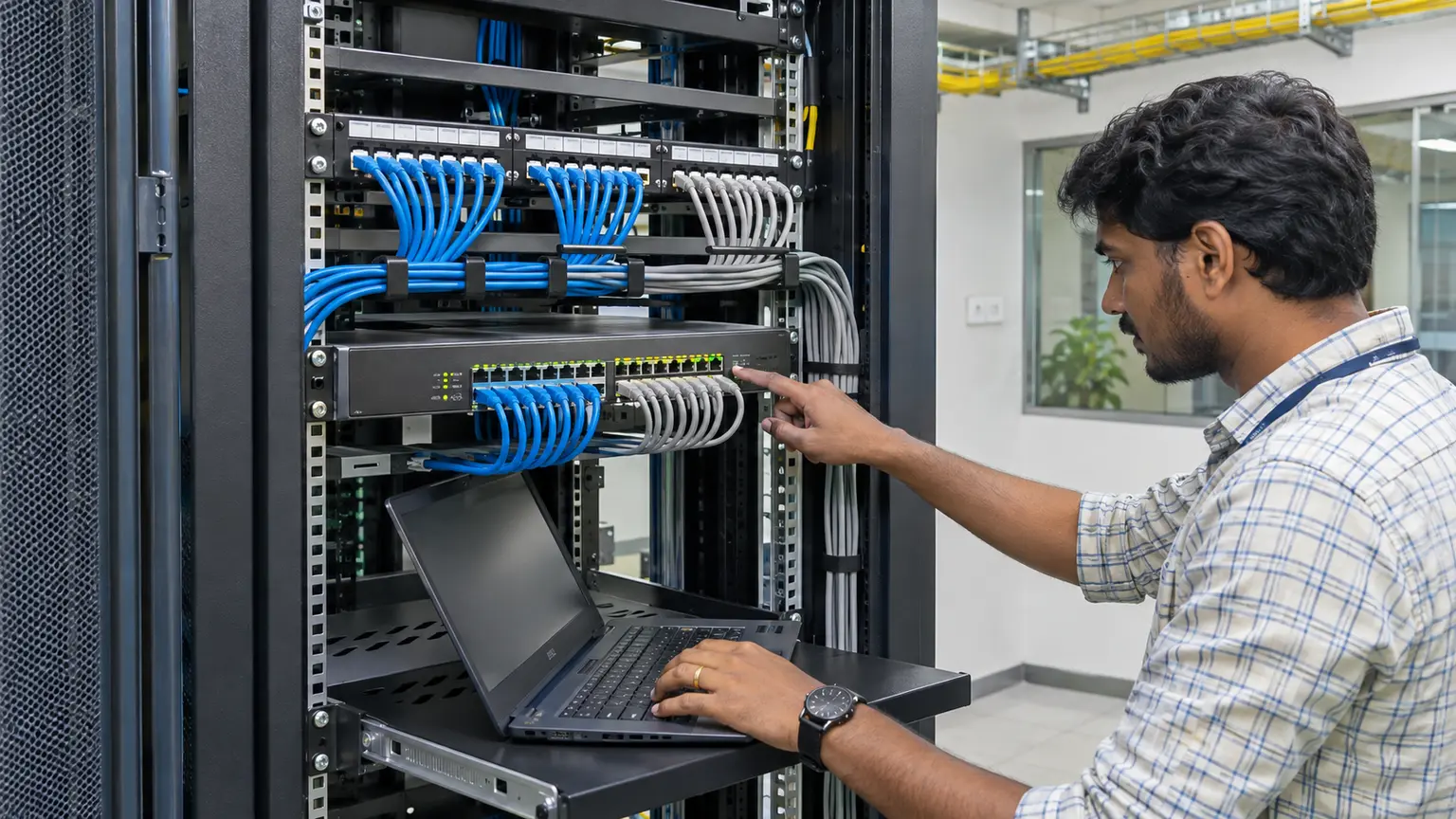
Record the switch model, software image, interface, data VLAN, voice VLAN, allowed VLAN list, port mode, authentication state, QoS trust boundary and PoE status. Confirm LLDP transmit and receive are enabled on the intended interface and that the network-policy TLV is selected. Check whether the platform advertises MED only after hearing a MED-capable endpoint.
The voice VLAN must exist end to end. Verify the uplink carries it, the gateway interface is available, DHCP scopes and options are correct, call-control routes are reachable and security policy permits required services. A perfect access-port advertisement cannot repair a missing trunk VLAN or exhausted DHCP scope.
4. Measure the complete boot sequence
Power-cycle the phone from the switch and timestamp the stages. Observe initial PoE detection, link establishment, LLDP reception, voice-policy application, DHCP, time synchronization, configuration download, call-control registration and stable service. A phone may first use the untagged network and then restart its network stack after learning the voice VLAN.
Time voice policy is applied - time Ethernet link becomes operational
Registration time
Time call service becomes ready - time PoE is enabled
Move recovery time
Time service is ready on the destination port - time the original link is removed
Measure at least three cold boots for each representative phone model and firmware. Record the median and worst observed time rather than creating a false universal target. Repeat after a switch restart if the building depends on large numbers of phones recovering together.
5. Prove the advertised network policy
Use detailed LLDP neighbor output on the switch and the phone network-status page. Confirm the application type is voice, the VLAN ID matches the design, the tagging flag is correct and PCP and DSCP values are intentional. Cisco documents network-policy examples with VLAN, CoS and DSCP, while Juniper describes application type, 802.1Q tagging, 802.1p priority and Diffserv fields.
Capture traffic between the switch and phone when practical. Confirm LLDP frames contain the expected MED capabilities and network policy. Then verify real voice signaling and media frames leave the phone with the intended VLAN tag and markings. The advertised value and the transmitted packet must agree.
6. Test QoS as a path, not a label
PCP and DSCP in the LLDP-MED policy express the desired endpoint marking. They do not prove that the campus network trusts, queues or preserves those values. Check the access-port trust boundary, classification rules, queue mapping, uplink policy and WAN edge. A phone can mark correctly while an intermediate switch rewrites everything to best effort.
Generate a controlled concurrent data load and place test calls. Record loss, one-way delay, jitter and call stability using the organization's approved tools. Confirm the data client cannot obtain voice priority merely by setting a high DSCP value. The trust policy should distinguish the phone or authenticated voice service from an arbitrary PC behind it.
7. Reconcile PoE negotiation and switch capacity
LLDP-MED can exchange detailed power information, including requested value and priority, but platform behavior also depends on IEEE 802.3 power negotiation and configured maximums. Aruba notes precedence considerations when both 802.3 and MED power reporting are enabled. Cisco describes fine-grained power requests and the possibility of granting or denying a request according to the available budget.
Available switch PoE capacity - sum of accepted endpoint allocations
Degraded headroom
PoE capacity after one planned power-supply loss - required critical-phone allocation
Oversubscription ratio
Sum of maximum endpoint requirements ÷ available PoE capacity
Record allocated and measured power at idle, active call, speakerphone and accessory load. Test the intended priority behavior if the switch loses a power supply or reaches its budget. Coordinate this result with the separate PoE load-shedding design so emergency, security and operational phones retain the planned service.
8. Validate location without exposing unnecessary data
LLDP-MED location information can represent civic data or an emergency location identifier. Juniper documents civic location as information advertised to the endpoint for emergency calling. In India, confirm how the deployed calling platform actually uses this information before treating a configured TLV as emergency-service proof.
Use the minimum accurate record needed by the approved design, such as site, building, floor and room. Restrict configuration and discovery output to authorized administrators because LLDP inventory and location data can reveal network structure. Juniper explicitly notes that optional TLVs may contain sensitive information and can be disabled where they are not required.
9. Test fallback, failure and moves
Disable only the MED network-policy advertisement in a controlled window and observe the endpoint. Does it remain on its last VLAN, fall back to untagged traffic, use a locally stored value or lose registration? Repeat with ordinary LLDP disabled, with the voice VLAN absent from the uplink and with DHCP unavailable. Document each failure signature so support teams do not mistake a policy problem for a cabling fault.
Move the phone to another approved port and verify it learns the destination policy, releases old network state and registers with the correct location. Move it to an unauthorized or data-only port and confirm the security outcome. Repeat with a PC behind the phone to prove its data VLAN remains correct through moves and phone restarts.
10. Mixed-vendor interoperability matrix
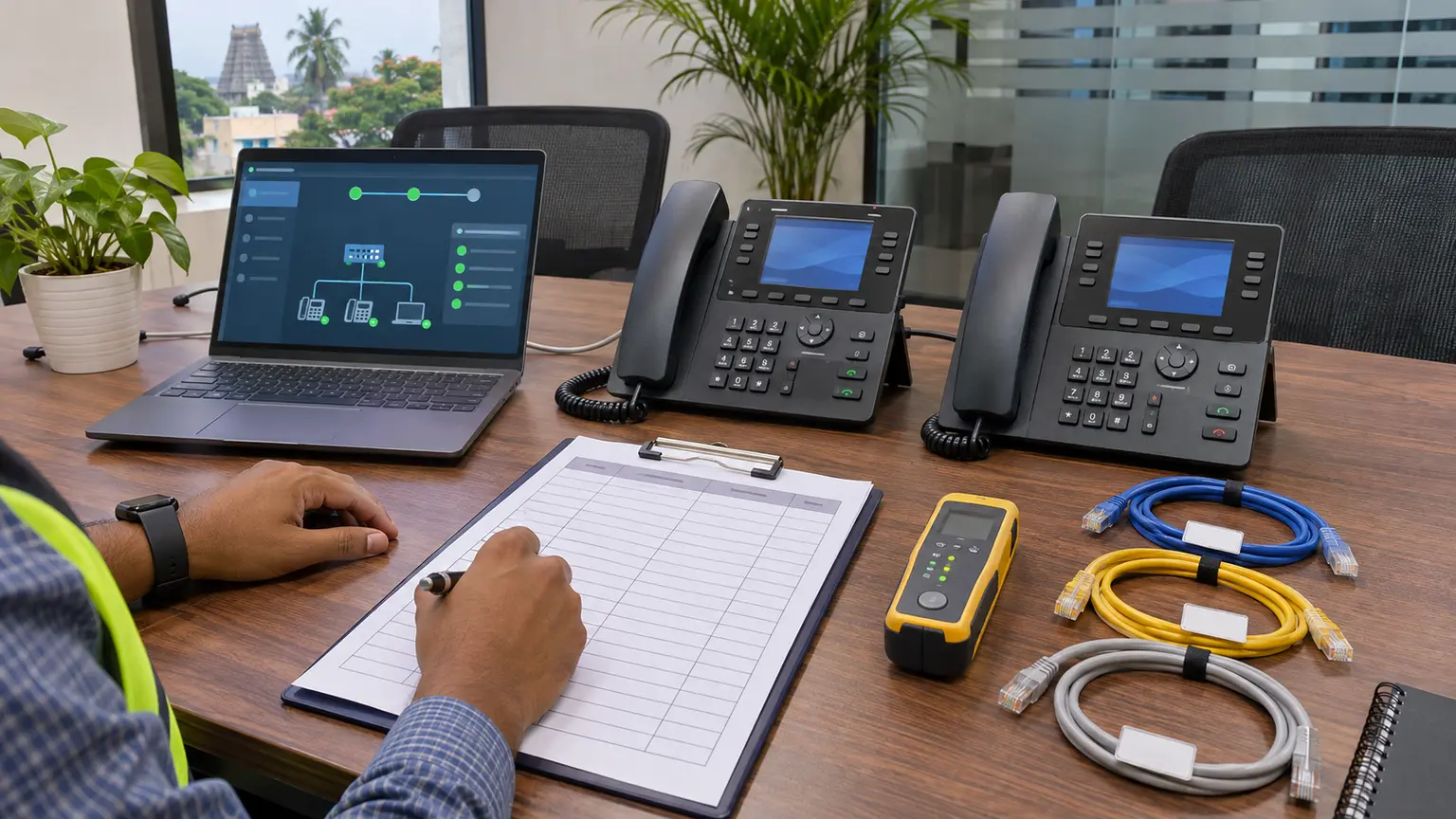
Test every switch family and every phone firmware that will be deployed. A single successful pair does not establish interoperability for the estate. Record whether the switch waits for an endpoint MED advertisement, how quickly the phone applies policy, whether it reboots its network stack, which power TLV is used and how the phone displays the learned values.
| Combination | Required result | Evidence |
|---|---|---|
| Switch family A, phone model 1 | Voice policy, PoE and location accepted | Neighbor detail, phone page, capture, call |
| Switch family A, phone model 2 | Same policy with model-specific timing recorded | Three boot samples and counters |
| Switch family B, phone model 1 | Equivalent behavior or approved exception | Configuration and exception record |
| Phone plus PC | Tagged voice and correct untagged data separation | Addresses, VLAN capture and access tests |
11. Acceptance checklist
- Switch model, software and phone firmware are recorded.
- Data and voice VLANs exist across access, uplink and gateway paths.
- LLDP transmit and receive are enabled on the intended port.
- MED capabilities and network-policy TLVs are observed.
- Voice application, VLAN, tagging, PCP and DSCP match the design.
- Phone traffic capture agrees with the advertised policy.
- PC traffic remains in the intended data VLAN.
- PC-to-phone separation and trust boundaries are verified.
- Cold boot policy-acquisition time is measured three times.
- DHCP, time, configuration and registration stages are timed.
- PoE requested, allocated and measured values are recorded.
- Normal and degraded switch power headroom are calculated.
- Concurrent data load does not destabilize approved calls.
- Location information is accurate, minimal and access-controlled.
- Missing-policy and missing-VLAN failure behavior is documented.
- Approved-port moves update network policy and location.
- Unauthorized-port behavior matches the security design.
- Configuration, captures, outputs, owners and regression triggers are handed over.
12. Handover worksheet
| Field | Required record |
|---|---|
| Port identity | Site, rack, switch, interface, outlet and user location |
| Endpoint | Phone model, firmware, MAC address and attached PC state |
| Policy | Voice VLAN, tagging, PCP, DSCP, data VLAN and trust boundary |
| Power | Standard, requested, allocated, measured, priority and reserve |
| Timing | Link, policy, DHCP, registration and move recovery timestamps |
| Evidence | Neighbor detail, packet capture, phone status, counters and call result |
| Operations | Fallback behavior, owner, escalation path and retest triggers |
Primary technical references
- Cisco IOS XE 26.x: Configuring LLDP, LLDP-MED and Wired Location Service
- Cisco Catalyst: LLDP-MED supported TLVs and power management
- HPE Aruba Networking AOS-CX 10.15 Fundamentals Guide
- Juniper Networks: Device discovery using LLDP and LLDP-MED
- Juniper Mist: LLDP-MED power negotiation
- Juniper Networks: Civic-based LLDP-MED location
Commissioning voice-ready LAN access?
Share the switch and phone models, VLAN plan, QoS policy, PoE capacity and location requirements. Cyber FTTH Mart can help structure port templates, interoperability tests and handover evidence for commercial facilities.
Discuss enterprise network commissioning ↗