
ENTERPRISE NETWORK RESILIENCE · 27 SEPTEMBER 2026
Switch redundancy and loop prevention: a commissioning worksheet
A second uplink does not automatically create a resilient network. If spanning-tree roles, aggregated links and failure behaviour are not designed and tested, extra cabling can produce blocked capacity, unstable topology or a damaging Layer 2 loop. This worksheet helps facilities teams and network owners accept redundancy through observed evidence rather than assumptions.
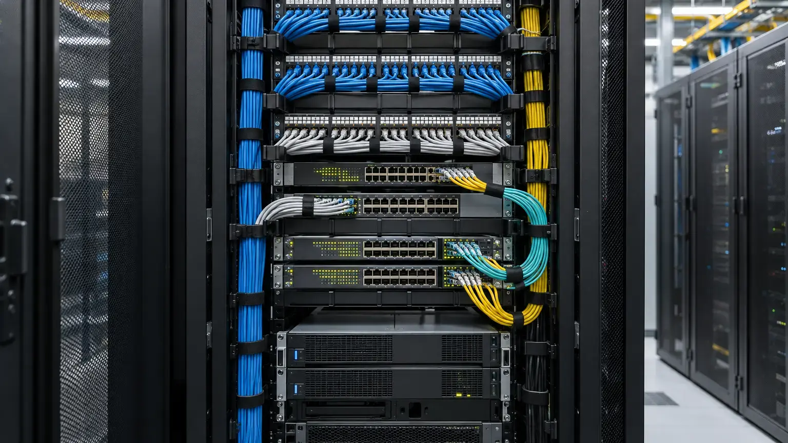
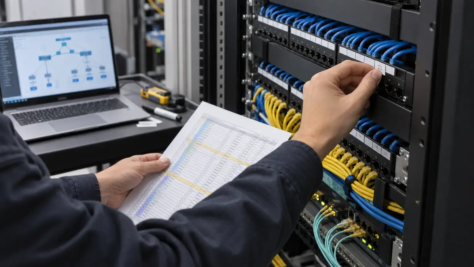
Visual reference photographs

Start with the intended failure behaviour
Before configuring switches, decide what should remain available when one uplink, one fiber, one switch, one power feed or one rack fails. Document the services affected, the permitted outage, the recovery method and the person responsible for approval. A design cannot be called redundant if nobody has defined which single failures it is expected to survive.
Draw the normal forwarding path and the alternate path for every important VLAN or service. Include core, distribution and access switches, routed boundaries, trunks, port channels, firewalls, servers, wireless controllers, CCTV recorders and management systems. Mark any component that remains a single point of failure.
Resilience row: service · normal path · alternate path · protected failure · expected impact · recovery target · test method · observed result · exception owner.
Document spanning-tree intent
The Cisco spanning-tree overview explains that STP prevents loops when switches are interconnected through multiple paths. During handover, record the STP or RSTP mode, bridge priorities, intended root and secondary root, VLAN or instance mapping, blocked ports and convergence expectations.
Do not accept a topology merely because it currently has no loop. Confirm that the intended switch becomes root after reboot, maintenance and replacement scenarios. An accidental root election at an access switch can change traffic paths and make a later failure much more disruptive.
Protect edge ports without hiding the design
Classify every port as edge, switch-to-switch, server, access point, camera, phone, firewall or another defined role. Apply edge-port and loop-protection features only according to the switch platform and approved design. Record which ports use PortFast, BPDU Guard, Root Guard, Loop Guard, UDLD or vendor equivalents, and why.
The official Cisco PortFast and BPDU Guard guide describes protections for ports that should not receive BPDUs. Cisco's Loop Guard and UDLD guidance explains that these controls address different failure conditions. Do not copy one setting to every port without understanding its purpose.
Verify each aggregated uplink as one logical link
For every LACP or other link aggregation group, record the logical interface, member ports, peer device, media type, speed, VLANs, native VLAN, negotiation mode, minimum active links and hashing method. Both ends must agree on the essential parameters.
The current Cisco EtherChannel configuration guide covers LACP operation, monitoring and configuration examples. Cisco also notes in its EtherChannel load-balancing and redundancy guide that an aggregated channel distributes traffic across member links. This does not mean one individual flow will automatically use the sum of all member bandwidth.
Port-channel evidence: channel ID · peer · member ports · member state · LACP state · allowed VLANs · link speed · error counters · test traffic · member-failure result · recovery result.
Test failures one at a time
Use an approved maintenance window and a written rollback plan. Establish a baseline first, including reachability, latency, packet loss, switch CPU, link utilization, interface errors, STP state, port-channel state and alarm status. Then introduce only one controlled failure at a time.
- Disconnect one member of an aggregated uplink and verify that the channel remains operational.
- Reconnect the member and confirm it rejoins cleanly without errors or an unexpected topology change.
- Disable the primary uplink and observe the alternate path, outage duration and affected services.
- Restore the primary path and confirm whether traffic returns as designed.
- Restart an access or distribution switch where the approved test plan permits it.
- Test loss of one fiber path without disturbing the parallel power or equipment path.
- Verify that monitoring receives link, topology and device alarms with correct timestamps.
- Confirm that DHCP, DNS, gateways, voice, Wi-Fi, CCTV and management remain available as expected.
Record actual observations, not only pass or fail. A test may preserve connectivity while causing unacceptable packet loss, long convergence, asymmetric routing, overloaded remaining links or loss of monitoring.
Watch for hidden shared dependencies
Two switch uplinks routed through the same fiber cable, duct, splice closure, patch panel, power circuit or UPS do not provide protection from failure of that shared element. The handover drawing should show physical path diversity, rack location and power source as well as logical topology.
Similarly, two access switches are not a resilient pair if both depend on one upstream interface, one firewall, one controller or one unprotected management path. List these limitations plainly instead of presenting partial redundancy as complete high availability.
Retain the evidence needed after handover
The final pack should contain approved topology drawings, device inventory, software versions, configuration backups, port and VLAN schedules, STP root and port-role output, port-channel status, interface counters, monitoring screenshots, test timestamps, observed interruption and unresolved exceptions. Remove passwords, private keys and sensitive configuration data from general handover copies.
- The intended root and secondary root are documented for every relevant instance or VLAN group.
- Blocked and forwarding ports match the approved topology.
- Every redundant uplink has a unique link ID and physical route reference.
- Every port-channel member is active, compatible and free of material errors.
- Edge-port safeguards are applied by documented port role.
- Unexpected topology changes generate a visible alarm or log event.
- Failure tests cover link loss, recovery and service impact.
- Remaining links have sufficient planned capacity during a failure.
- Physical path and power diversity are verified, not assumed.
- Configuration backups match the commissioned state.
- Exceptions have an owner, corrective action and closure date.
- The owner has a safe rollback and recovery procedure.
Commissioning worksheet
Create one sheet for topology intent, one for STP instances and root roles, one for aggregated links, one for edge-port protections, and one for controlled failure tests. Link each row to the relevant drawing, configuration evidence, monitoring record and acceptance signature.
Related reading: use the VLAN and switch handover worksheet for service and trunk mapping, the structured cabling and PoE worksheet for physical-link evidence, and the rack documentation worksheet for labels and records. See enterprise networking services for design, configuration, testing and handover scope.
Planning a resilient campus or building network?
Share the topology, switch schedule, fiber routes, VLAN plan, critical services and recovery expectations. We can structure the switching, uplinks, testing and handover documentation around the actual project.
Discuss the network project ↗