
CCTV INFRASTRUCTURE · 25 SEPTEMBER 2026
Outdoor CCTV surge protection and grounding: a pre-handover worksheet
An outdoor camera can stream correctly on commissioning day and still remain vulnerable at the first major electrical disturbance or monsoon exposure. This worksheet helps builders, facilities teams and integrators record the cable route, surge-protection position, grounding path, enclosure condition and acceptance evidence for each outdoor CCTV point.
Visual reference photographs
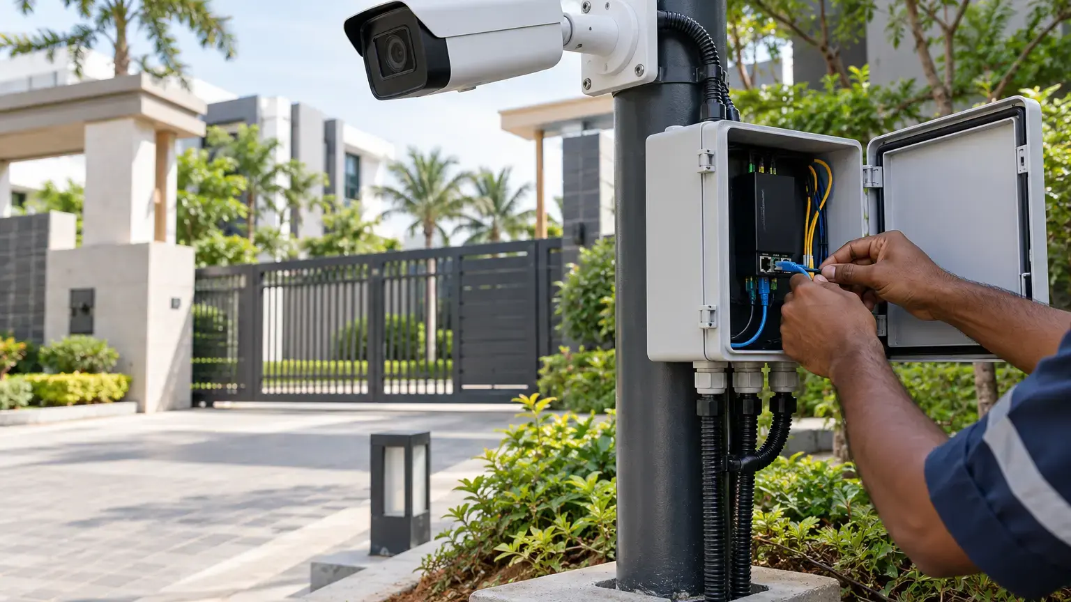


Start with the complete route, not only the camera
For each outdoor camera, draw the path from the camera to the PoE switch, injector or field cabinet and then to the control room. Mark every transition between outdoor and indoor space, every pole or wall cabinet, every copper section, every fiber section, and every point where power enters the system. A surge-protection device cannot be selected or positioned sensibly without this route information.
The official Axis T8061 product guidance describes placement immediately beside an outdoor camera or before an Ethernet cable enters a building. That placement principle is useful during design review, but the selected device and grounding method must still match the camera, PoE standard, cable, electrical design and manufacturer instructions.
Route record: camera ID · pole or wall location · cable type · copper length · fiber segment · enclosure ID · building entry point · switch or injector · power source · drawing reference.
Separate weather protection from surge protection
An IP-rated camera does not automatically protect the network cable, connector, field enclosure or equipment inside the building. Check the camera gland, drip loop, connector seal, cabinet door gasket, conduit entry, unused openings and the direction from which water can travel along the cable. Record the enclosure rating and whether the installed glands preserve it.
The Axis P13-E installation guide requires outdoor-rated shielded network cable and a properly grounded endpoint for the covered installation. It also warns that using a cable gland other than the supplied type can allow water ingress. Use the instructions for the exact installed camera, because gland sizes, shield requirements and permissible mounting methods vary by model.
Verify the grounding path as an engineered system
A surge protector needs a defined path for diverted energy. Record the grounding conductor, bonding point, conductor routing, connection hardware and the party responsible for electrical approval. A label saying grounded is not evidence that the connection is suitable, continuous or coordinated with the building earthing system.
Do not improvise a separate earth rod, bond to an unknown metal part or assume that any shield termination is correct. The grounding and bonding arrangement should be reviewed by a qualified electrical professional against the site electrical design, local requirements and the installation instructions for the selected equipment.
Grounding evidence row: protector ID · protected line · mounting location · grounding terminal · conductor size · conductor route · bonding point · inspection result · electrical approval reference · photograph filename.
Check PoE and data compatibility before selection
Confirm the highest data rate, PoE type, maximum power, connector type and environmental rating required by the installed link. The Axis T8061 page states support for up to 1 Gbps, outdoor installation and protection for PoE devices, but those specifications should not be generalized to another surge protector. Verify the actual datasheet for every selected model.
After installation, test the camera under its maximum expected load. Confirm live video, infrared or white-light operation, heater or blower operation where present, PTZ movement where applicable, analytics, audio and any I/O. A link that passes with the camera idle may still fail when the PoE load increases.
Use fiber where electrical isolation and distance justify it
For widely separated buildings, long outdoor routes or electrically noisy areas, a fiber segment can remove a conductive data path between locations. Fiber does not remove the need to protect local power, outdoor cabinets, media converters or copper camera drops. Document exactly where copper ends, where optical conversion occurs, and how each powered field device is protected.
Keep spare fiber cores, splice records, termination labels and optical test results in the handover pack. Where a field switch serves several cameras, record the impact of one cabinet or power failure so the owner understands the real fault domain.
Witness realistic handover tests
- Each outdoor camera and enclosure has a unique asset ID.
- The as-built drawing shows the complete path from camera to recorder or core network.
- Outdoor cable, connectors and glands match the equipment instructions.
- Cabinet entries are sealed and unused openings are closed.
- Surge protectors are identified at the camera, field cabinet and building entry points where the design requires them.
- Every protector is compatible with the installed Ethernet speed and PoE load.
- The grounding and bonding path is documented and approved by the responsible electrical professional.
- Protective devices and grounding conductors are accessible for inspection without disturbing unrelated services.
- The camera operates with infrared, heater, PTZ, analytics and other maximum-load functions enabled where applicable.
- Link speed, packet stability and PoE status are checked after protection devices are installed.
- Fiber segments have core IDs, splice records and optical test results.
- Field cabinets record switch, media-converter, power-supply, UPS and protector models.
- Final photographs show the camera entry, enclosure interior, protector, grounding connection and cable labels.
- Exceptions have an owner, corrective action and closure date.
Outdoor CCTV protection worksheet
Create one row per camera or field cabinet. Include camera ID, location, mounting type, cable route, cable category, PoE source, copper length, fiber link ID, surge-protector model and serial number, protector position, grounding point, enclosure rating, gland and seal condition, link test, maximum-load test, photograph references, exception status and acceptance signature.
Related reading: use the villa CCTV design worksheet for view planning and field architecture, the structured cabling and PoE worksheet for link evidence, and the CCTV cybersecurity worksheet for accounts, network isolation and recovery. For delivery scope, see CCTV and surveillance services.
Planning outdoor cameras, poles or fiber-linked CCTV cabinets?
Share the site plan, camera schedule, pole locations, cable routes, power sources and control-room design. We can structure the network, fiber backhaul, PoE, testing and handover documentation around the actual project.
Discuss the CCTV project ↗