

ENTERPRISE POE RESILIENCE · 27 OCTOBER 2026
PoE power budget and load shedding: a commissioning worksheet
A switch can have enough Ethernet ports and still be unable to power every camera, access point, phone, intercom or door controller after startup, a power-supply failure or a configuration change. This worksheet turns the PoE budget into a service-priority plan and proves what stays online when available power falls.
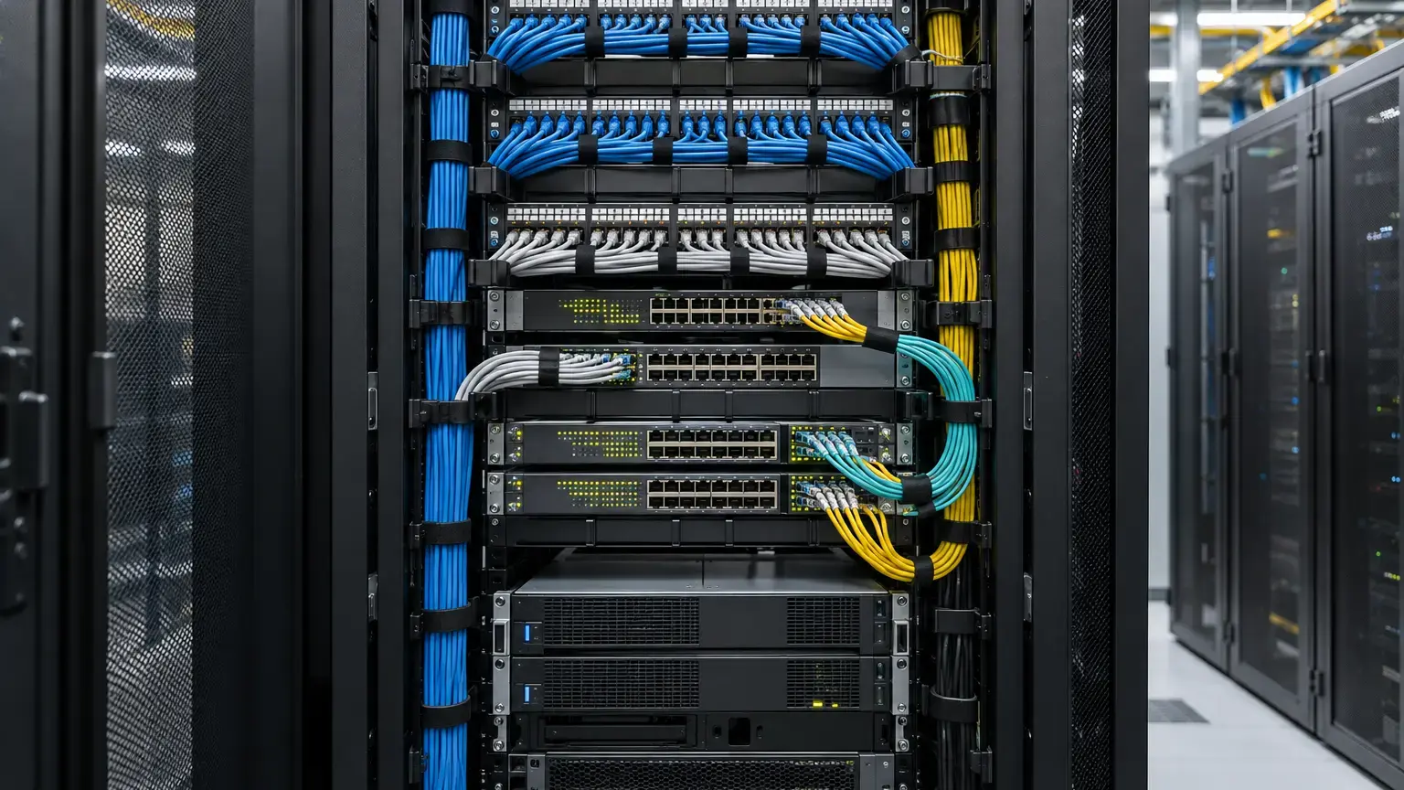
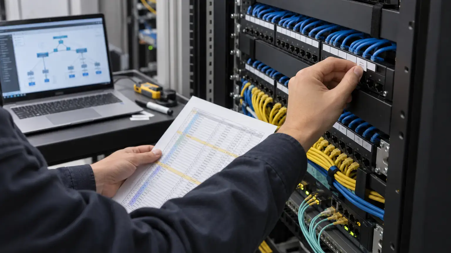
Visual reference photographs

Separate port capability from the shared power budget
A PoE-capable port rating does not mean that every port can deliver that rating simultaneously. The switch has a shared budget determined by its chassis, power supplies, modules, redundancy mode and software. Cisco documents that its switch tracks available PoE power, grants or denies requests and updates the budget as devices negotiate. Juniper likewise separates chassis or line-card power allocation from the PoE controller's port allocation.
Record three different quantities: the power the powered device can require, the power the switch reserves or allocates, and the live power currently drawn. Idle draw is useful for trending, but it is not a safe design value for a camera when IR LEDs and heaters are off, or for an access point before radios, USB or downstream PoE features are active.
Device row: service ID · switch and port · powered-device model · IEEE PoE type or class · required input power · PSE allocation · measured draw · operating mode · priority · outage consequence.
Check the exact PoE type and negotiation method
IEEE 802.3bt introduced Type 3 and Type 4 operation with four-pair powering and additional classes. Ethernet Alliance's Gen 2 technical brief lists up to 60 W at the PSE and 51 W at the powered device for Type 3, and up to 90 W at the PSE and 71.3 W at the powered device for Type 4. The difference accounts for delivery losses and is why a device's input requirement must not be compared directly with a marketing total for the switch.
Confirm whether the switch port and powered device use physical classification, LLDP, a vendor discovery protocol or a product-specific mode. Cisco notes that initial allocation can be adjusted through CDP or LLDP. A third-party device cannot rely on Cisco-only CDP. Capture both the detected class and the negotiated allocation after the device has fully booted.
Prefer standards-based, interoperable combinations. Ethernet Alliance certification identifies products tested against its IEEE 802.3 PoE program. Treat passive PoE and proprietary modes as separate designs with explicit voltage, polarity, connector and equipment controls. Do not assume they are safe substitutes for IEEE detection and classification.
Calculate normal and degraded budgets
Use allocated or worst-case PSE power for design, then compare live measurements separately. Group devices by the switch or stack member that actually supplies them.
Required PoE budget (W) = sum of planned per-port allocations + engineering reserve
Normal headroom (W) = normal available PoE budget − required PoE budget
Degraded headroom (W) = available PoE budget after one approved failure − required critical-load allocation
PoE utilization (%) = reserved PoE power ÷ available PoE budget × 100
Example: 12 cameras allocated 15.4 W each, 6 access points allocated 30 W each and 4 door controllers allocated 12 W each total 412.8 W. Adding a documented 15 percent engineering reserve gives 474.72 W. A 740 W normal budget has 265.28 W headroom. If a power-supply failure reduces the available PoE budget to 370 W, the complete planned load cannot be retained. The design must nominate which services shed, reduce allocation or move to another power domain. Figures are illustrative only.
Do not count power-supply nameplate capacity twice. Some switches use the same supply for switch operation and PoE. Cisco's industrial-switch guidance explicitly requires subtracting the switch's own requirement when raising the PoE budget on a shared supply. Use the exact platform documentation and installed PSU combination.
Design load shedding by service consequence
Port priority is an operational control, not a label. Cisco documents load shedding after a power-supply failure, with lower-priority devices disconnected first. Juniper documents the same principle and notes that equal-priority decisions can fall back to port order. Therefore, leaving every port at its default can make physical port numbering decide which services survive.
Create a priority matrix before configuration. Life-safety systems require their own approved design and must not be treated as ordinary IT loads. For the remaining building network, a project might classify entrance access controllers and essential intercoms as critical, selected perimeter cameras and operational Wi-Fi as high, and convenience-area devices as low. The actual order must be agreed by the owner and each service stakeholder.
Priority matrix row: service · device count · ports · allocated watts · priority · acceptable outage · degraded feature set · recovery order · owner approval.
Check whether LLDP power-priority information can override locally configured priority. Juniper documents an option in which an LLDP-enabled device supplies the priority assigned by the switch. Record which authority wins on the installed platform, and do not allow an endpoint default to silently replace the agreed service matrix.
Allow for startup and real operating modes
PoE startup includes detection, classification and controlled inrush. Microchip describes inrush as a managed phase that charges the powered device before steady operation. A large group of devices starting together after a mains return can behave differently from the same group already running at idle.
Commission representative high-demand modes: camera IR illumination and heaters where fitted, PTZ movement, access-point radio load, USB accessories, downstream PoE, display brightness, door strikes and alarm outputs. Verify which features a device disables when it receives less than its preferred allocation. A link light and management response do not prove that every intended function is available.
Stage a cold start of the approved device group and review PoE denials, class errors, power-policing events, repeated boot cycles and negotiation changes. Avoid repeatedly interrupting access-control or surveillance services without an agreed maintenance window and rollback plan.
Test the failure case, not only the spreadsheet
- Save the normal power inventory, allocations, live draw, priorities and alarm state.
- Confirm the UPS, power supplies and redundant feeds are in their intended normal mode.
- Place representative devices in their high-demand operating states.
- Under an approved method, remove one redundant PSU or input feed that the design claims to tolerate.
- Record the new available PoE budget and the exact order of any device shutdowns.
- Confirm critical services remain fully functional, not merely reachable.
- Verify alarms identify the failed supply and any shed ports.
- Restore the supply and record device recovery order, boot time and service restoration.
- Check for devices that remain denied, restricted or error-disabled after power returns.
- Compare observed behavior with the approved priority matrix and correct discrepancies.
If the switch cannot safely simulate the intended failure, use the manufacturer's supported test method or document the limitation. Do not pull a live module merely to demonstrate redundancy unless the platform and change procedure explicitly permit it.
Use power policing carefully
Power policing can protect a switch when a device exceeds its allocation, but an incorrect ceiling can shut down a legitimate device during a high-demand mode. Cisco's current configuration guide warns that the policing cutoff is not simply the configured value and must account for cable loss. It also recommends policing on supported switches.
Set limits from the powered-device specification, PSE method and platform guidance. Test the intended peak function after applying them. Record whether a violation logs an event, removes power, places the port in an error state or recovers automatically. Manual allocations used to make a spreadsheet fit can create an unstable network if devices later draw what they actually require.
Commissioning worksheet
- Installed switch, modules, PSU models and software release are recorded.
- Normal and single-failure PoE budgets are confirmed from the exact platform configuration.
- Every powered device maps to a port and service owner.
- Required PoE type, class, pair mode and input power come from the device specification.
- Detected class and negotiated allocation are captured after full boot.
- LLDP or vendor-protocol dependencies are documented.
- Reserved power is separated from live measured draw.
- Normal headroom and degraded critical-load headroom are calculated.
- Engineering reserve is stated and approved, not hidden in device figures.
- Port priorities match the service matrix.
- The precedence of local versus LLDP priority is verified.
- Representative peak device modes are tested.
- A coordinated cold start produces no unexplained denial or reboot loop.
- The approved PSU or feed failure sheds only the intended ports.
- Critical functions remain operational in degraded mode.
- Power, port and service alarms reach the monitoring team.
- Restoration returns every device to its intended allocation and feature set.
- Native command outputs, calculations, exceptions and sign-off enter the handover pack.
Minimum handover pack
Provide the switch and PSU inventory, software version, device-to-port schedule, device power requirements, detected classes, negotiated allocations, normal and degraded budget calculations, reserve policy, priority matrix, power-policing settings, cold-start record, failure and recovery results, alarm evidence and approved exceptions. Link it to the structured cabling for PoE worksheet, rack UPS runtime worksheet and rack labeling and documentation worksheet.
Primary technical references
- Ethernet Alliance: Gen 2 PoE Certification technical brief
- Ethernet Alliance: PoE Certification
- Cisco: PoE Configuration Guide
- Cisco: Power over Ethernet and load shedding
- Juniper: PoE User Guide for EX Series Switches
- Microchip: PoE inrush, power-up and disconnect
Commissioning PoE for CCTV, Wi-Fi or access systems?
Share the switch and PSU models, powered-device schedule, port map, redundancy plan and UPS target. We can coordinate structured cabling, switch configuration, power-budget checks and witnessed failure testing around the approved design.
Discuss PoE commissioning ↗