
OPTICAL FIBER DOCUMENTATION · 26 SEPTEMBER 2026
Fiber core allocation and route records: an as-built handover worksheet
A fiber backbone is difficult to operate when the drawing shows a cable but does not show what each core does. This worksheet helps builders, facilities teams, LCOs, MSOs and ISPs connect every route, cable, tube, fiber, splice, termination, service and test result in one controlled as-built record.
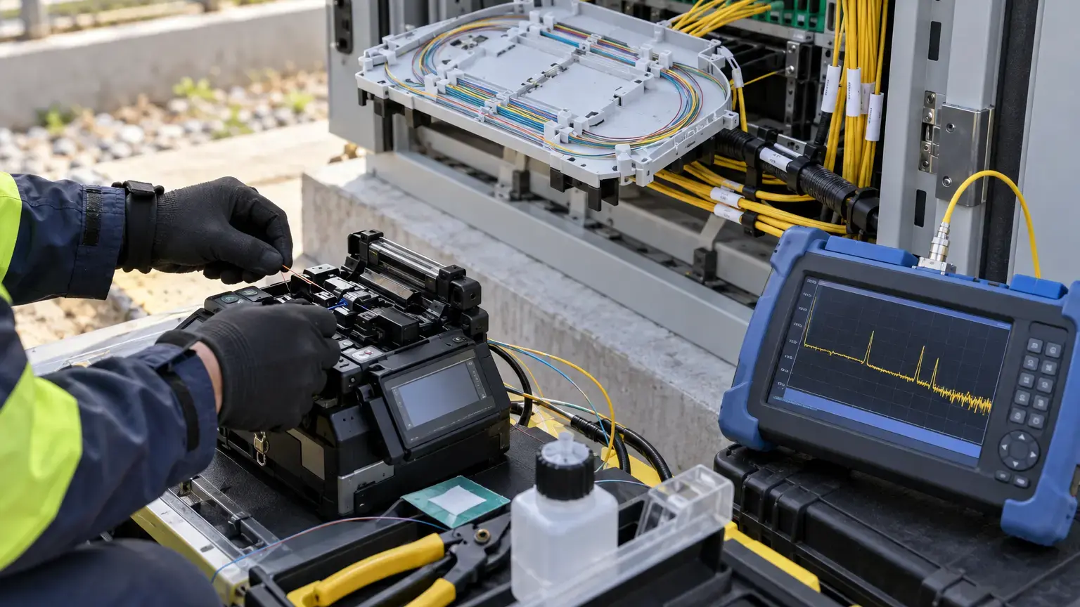
Visual reference photographs


Why the cable route and core schedule must be one record
A route drawing alone tells the maintenance team where a cable runs. A core schedule alone tells them that a fiber is assigned. Neither record is enough if the identifiers do not connect. The handover pack should let a technician start at a service or port, identify the fiber and tube, follow every splice, locate the physical cable route and open the correct test result without guessing.
The FOA installation standard states that documentation is required for premises and outside-plant cable installations, with outside-plant records also including route-location data. The FOA outside-plant design guide also recommends protecting cable-plant records and retaining backup copies because they are essential during maintenance and restoration.
Traceability test: choose any live service and confirm that another engineer can find its rack port, adapter, pigtail, splice tray, fiber number, tube number, cable ID, route section, far-end termination and test file using only the handover pack.
Create stable identifiers before entering data
Use one naming system across drawings, cable tags, joint closures, ODFs, patch panels, FATs, FDBs, splice trays and test filenames. Avoid labels such as cable 1 or spare fiber when several buildings, shafts or phases exist. A practical identifier can combine site, building or zone, route section, cable sequence and endpoint.
Do not renumber existing assets casually during an extension. Record the old identifier, new identifier, reason, date and approving person so earlier test reports and fault records remain usable.
Build the route register first
Create one row for every installed cable section. Record the cable ID, start and end points, route type, approximate installed length, manufacturer and model where available, fiber count, fiber type, duct or tray reference, chamber or handhole sequence, joint locations, entry seals, slack-loop locations and drawing reference. For outside plant, include coordinates or GIS references where the project maintains them.
Separate designed length from installed length and measured optical length. They answer different questions and should not be presented as interchangeable values.
Make the core-allocation table granular
Use one row per fiber core, not one row per cable. Record cable ID, tube or bundle, fiber number and color, near-end termination, far-end termination, intermediate splice references, service or customer, equipment port, operational status, reservation owner, test-record filename and last-change date.
Use controlled status values such as live, allocated, dark spare, reserved, faulty, under test and decommissioned. A blank cell should never be interpreted as a spare core. If a core is intentionally unused, mark it explicitly as a dark spare and record whether it is terminated, looped, sealed or available only after future splicing.
Minimum allocation row: cable ID · tube · fiber number · color · A-end port · B-end port · splice references · service · equipment port · status · test-file reference · change date · approved by.
Connect splice and termination records
Every joint closure or splice tray should have a unique ID that appears on the route drawing and in the splice schedule. Record incoming cable and fiber, outgoing cable and fiber, splice type, tray position, protection sleeve position, date, technician and test reference. At terminations, record enclosure, panel, adapter and port identifiers at both ends.
For PON networks, distinguish feeder, distribution and drop segments. Record splitter location, splitter ID, ratio, input fiber, output port and downstream destination. Do not use one broad label for an entire PON when individual branches must be located and maintained.
Keep capacity truthful
Report total cores, live cores, allocated but not active cores, usable dark spares, reserved cores, faulty cores and cores unavailable because of incomplete splicing or termination. This prevents a procurement or operations team from assuming that every unlit core is immediately usable.
For multi-building or phased projects, show capacity by route section. A backbone may have spare capacity at the control room while a later branch or riser is already full.
Link tests without duplicating results
The core schedule should point to the approved loss-test and OTDR files rather than copying selected readings into several uncontrolled spreadsheets. Use filenames that include the link or core ID, direction, wavelength, test date and revision. Confirm that the identifier inside the test file matches the field labels and allocation table.
The FOA installation deliverables guide treats documentation and test results as part of the completed cable plant, not optional paperwork. The FOA testing reference explains the need for continuity, polarity and insertion-loss testing, with OTDR verification commonly used for long outside-plant links with intermediate splices.
Use controlled changes after handover
Keep one approved master register with revision, issue date, change description and approver. Field teams may use working copies, but every move, addition, repair or decommissioning must return to the master record. Retain previous revisions so fault investigations can reconstruct the network state at an earlier date.
- Every cable, joint, enclosure, panel and port has a unique field label.
- The route drawing and cable register use identical cable IDs.
- Every installed core has an explicit status.
- Live and reserved cores identify the service or reservation owner.
- Every splice maps incoming and outgoing fibers.
- Every termination identifies enclosure, panel and port.
- PON splitter inputs and outputs map to downstream destinations.
- Dark spares state whether they are terminated and tested.
- Faulty cores include the fault reference and corrective-action status.
- Test filenames contain the same link or core ID used in the register.
- OTDR traces and loss results are linked without uncontrolled duplication.
- Route records show chambers, joints, building entries and slack locations.
- Installed length and measured optical length are identified separately.
- Capacity summaries distinguish usable spares from unavailable cores.
- The final pack has a revision number, approver and protected backup copy.
As-built handover worksheet
Prepare five linked sheets: route register, cable and core schedule, splice schedule, termination and port schedule, and test-file index. Add a sixth change register for all work after acceptance. Use the same identifiers in every sheet, on every drawing and on every physical label.
Related reading: use the fiber testing acceptance guide to structure measurement evidence, the fiber restoration worksheet for fault response, and the connector inspection guide before testing. See optical fiber cabling services for survey, laying, splicing, testing and documentation scope.
Need a usable fiber as-built pack?
Share the route drawings, cable schedule, splice plan, termination list and available test files. We can structure the field labels, core-allocation register, test references and handover records around the installed network.
Discuss the fiber project ↗