

OPTICAL FIBER TESTING · 29 OCTOBER 2026
Fiber reflectance and optical return loss: a field acceptance worksheet
A link can meet its insertion-loss budget and still contain a highly reflective connector, air gap, mechanical splice or open end. These reflections can disturb laser-based systems and hide poor workmanship. This worksheet separates individual-event reflectance from whole-link optical return loss and turns both into traceable field evidence.
Visual reference photographs
Separate reflectance from optical return loss
Reflectance describes the fraction of launched power returned by one event, such as a connector. It is normally shown as a negative dB value. A more negative value represents less reflected power. Optical return loss, or ORL, is normally a positive value representing the ratio between launched power and total returned power.
OTDR manufacturers commonly use ORL for the combined return from all reflective events plus distributed fiber backscatter over the selected link. That whole-link value is not the same as the reflectance of one connector. Keep the metric name, sign and scope in every result.
Reflectance (dB) = 10 log10(reflected power ÷ incident power)
Return loss (dB) = -10 log10(reflected power ÷ incident power)
The same ratio can therefore appear as -50 dB reflectance or 50 dB return loss.
Why a low-loss event can still be a problem
Insertion loss measures power that does not continue forward. Reflectance measures power returned toward the source. A connector can show modest forward loss while still reflecting enough light to affect a sensitive laser system. Multiple reflections on short single-mode links can also add background noise.
FOA identifies connectors and mechanical splices as common reflective events. A properly made fusion splice should normally be nonreflective. A reflection at a supposed fusion splice can indicate incomplete fusion, an air inclusion, contamination or incorrect event mapping.
Freeze the acceptance requirement
Do not copy one generic ORL limit across GPON, XGS-PON, Ethernet, CATV and transport links. Obtain the transmitter, receiver, interface and passive-component requirements from the approved system design and manufacturer documentation. Record whether the limit applies to individual event reflectance, component return loss, whole-link ORL or all three.
Requirement row: link ID · application and wavelength · transmitter and receiver · connector type · event reflectance limit · whole-link ORL limit · direction · test method · source document and revision.
Control connector type and polish
Physical-contact polishing reduces the air gap and reflection. APC connectors use an angled end face to direct reflected light away from the fiber core and typically provide better return-loss performance than flat or UPC connections. Do not mate APC and UPC connectors. They differ in geometry and are commonly color-coded, but acceptance must use part numbers and inspection rather than color alone.
Record every connector and adapter in the tested path. An unexpected adapter, hybrid patch cord, damaged ferrule or open branch can dominate the return signal even when most components are good.
Inspect and clean before every measurement
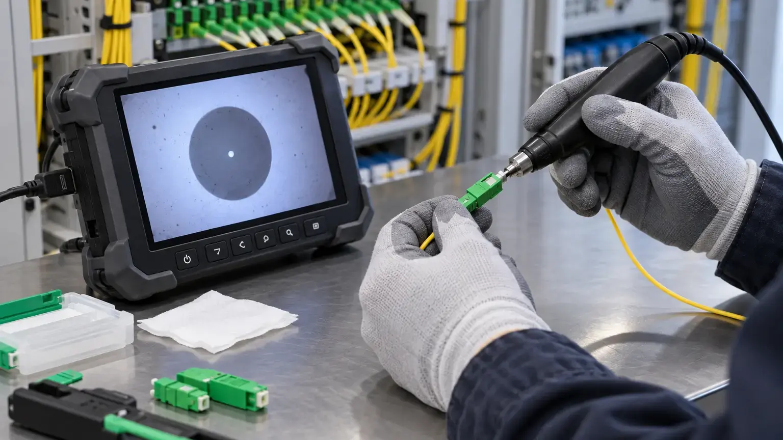
Reflectance is highly sensitive to contamination. Fluke notes that dirty end faces can degrade return loss substantially. EXFO recommends inspecting and cleaning test jumpers, equipment ports and link connectors with the correct probe and accessories.
Confirm that the fiber is not connected to an active optical source before inspection. Use an approved live-fiber detection procedure and instrument where required. Inspect, clean when needed and reinspect before mating. Save inspection images for failed and final states without claiming that visual inspection replaces optical testing.
Build an OTDR setup that can see the end connectors
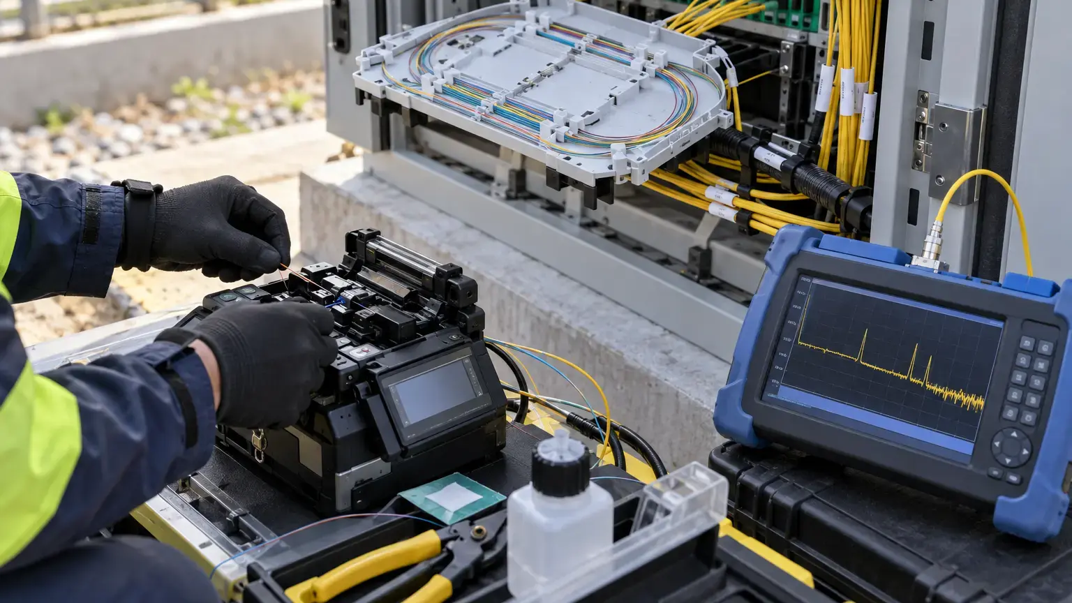
Use a launch fiber before the link and a receive fiber after it. These place the first and last connectors outside the OTDR dead zones and allow their reflectance to be measured. Record launch and receive cord IDs, fiber type, connector polish, length and inspection status.
Select range, pulse width, averaging time, index of refraction and event thresholds for the link. A long pulse may increase reach but can saturate reflective events and merge nearby connections. A flat-topped reflection peak indicates receiver saturation and makes the reported reflectance unreliable.
OTDR setup row: instrument and serial · calibration status · software · wavelength · range · pulse width · averaging · IOR · launch cord · receive cord · event threshold · ORL span · operator.
Test at the operating wavelengths
Reflectance and ORL can vary with wavelength and component behavior. Test the wavelengths required by the project and equipment. Keep live PON safety in scope: do not attach an ordinary unfiltered OTDR to an active network. Use a suitable in-service method and wavelength only when approved by the operator and instrument manufacturer.
Save native traces, not only screenshots or printed summaries. The native file preserves settings, cursors, event table and future reanalysis capability.
Measure in both directions
Fluke recommends bidirectional OTDR testing because event results depend on direction and the backscatter properties of the adjacent fibers. Pair the A-to-B and B-to-A events by physical location and records. Use the same wavelength and comparable settings.
Do not average signed reflectance values casually. Preserve each directional result and follow the project or instrument method for the final reported metric. If one direction saturates or cannot resolve the event, record the limitation and retest with an appropriate pulse or setup.
Calculate reflected-power ratio for diagnosis
The dB value can be translated into a ratio to explain severity:
Reflected power fraction = 10^(reflectance dB ÷ 10)
Reflected power percentage = 100 × 10^(reflectance dB ÷ 10)
Illustrative examples: -20 dB reflectance equals 1 percent returned power, -40 dB equals 0.01 percent and -60 dB equals 0.0001 percent. These ratios explain the scale but are not universal acceptance limits.
Respect measurement uncertainty
FOA notes that reflectance measurements can have uncertainty around plus or minus 1 dB in single-mode testing, even when an instrument displays hundredths of a dB. Display resolution is not accuracy. Avoid declaring a component conclusively better based on a tiny difference below the method's uncertainty.
Record repeatability. If three measurements vary widely after remating, investigate cleanliness, adapter condition, launch connection, polarization sensitivity, saturation and event placement.
Repeatability spread = highest measured dB value - lowest measured dB value
Compare the spread with the approved measurement method and instrument specification before judging the link.
Troubleshoot one reflective event at a time
Map the OTDR event to the patch panel, closure, adapter or mechanical splice. Inspect and clean accessible connectors, then remate and retest without changing unrelated components. Replace a suspect adapter or patch cord only after documenting the original state.
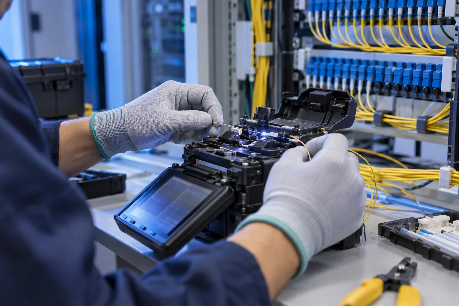
An open fiber end creates a strong Fresnel reflection. A broken fiber, poorly mated connector, air gap, crack or contaminated end face can appear reflective. Mechanical splices depend on correct cleaves, alignment and index-matching material. A reflective fusion splice should be re-examined rather than accepted solely because its insertion loss is low.
Use ORL and event reflectance together
Whole-link ORL can identify an overall return problem, while event reflectance localizes likely causes. A passing ORL total does not automatically approve every connector if the contract sets event limits. A failed total does not identify which event to repair.
After corrective work, repeat the same direction, wavelength and setup, then confirm the whole-link ORL and individual event results. Also verify insertion loss because a change can improve reflection while introducing forward loss or vice versa.
Field acceptance worksheet
- The application-specific event and whole-link limits are approved.
- Reflectance and ORL names, signs and scopes are unambiguous.
- Fiber type, connector polish, adapters and wavelengths are recorded.
- APC and UPC interfaces are never directly mated.
- Test ports, cords and link connectors are inspected and cleaned.
- Live-fiber safety and operating status are confirmed.
- Launch and receive cords expose both end connectors.
- Instrument calibration, software and settings are recorded.
- Pulse width avoids unnecessary dead zones and saturation.
- Required operating wavelengths are tested.
- A-to-B and B-to-A native traces are saved.
- Each reflective event maps to a physical component or documented exception.
- Whole-link ORL and individual-event reflectance are evaluated separately.
- Measurement uncertainty and repeatability are considered.
- Failed events are corrected one controlled component at a time.
- Final insertion loss is rechecked after reflectance correction.
- Before and after traces retain the repair history.
- Results, settings, inspection images and exceptions enter the handover pack.
Minimum handover pack
Provide the approved limits, link and component schedule, connector-polish record, instrument and calibration details, launch and receive cord register, inspection images, bidirectional native traces, event map, individual reflectance table, whole-link ORL results, repeatability checks, corrective-work history, final insertion-loss results and approved exceptions. Link this to the connector inspection worksheet, bidirectional OTDR worksheet and active optical-link worksheet.
Primary technical references
- FOA: Measuring reflectance or return loss
- FOA: Fiber optic testing FAQs
- Fluke Networks: Return loss causes and testing
- Fluke Networks: Reflectance and ORL measurement
- EXFO: Optical connector and fiber inspection
- ITU-T G.671: Passive optical component characteristics
Investigating reflective events or unstable optical links?
Share the cable route, connector types, application, wavelengths, insertion-loss record and native OTDR files. We can coordinate inspection, trace review, controlled correction and final acceptance evidence.
Discuss fiber testing and restoration ↗