

OPTICAL FIBER TESTING · 26 OCTOBER 2026
Bidirectional OTDR testing: a fiber acceptance worksheet
One OTDR trace can locate events, but it can misstate an individual splice loss when joined fibers scatter light differently. A defensible acceptance record pairs traces from opposite directions, preserves the launch and receive conditions, and averages matching event results.
Visual reference photographs
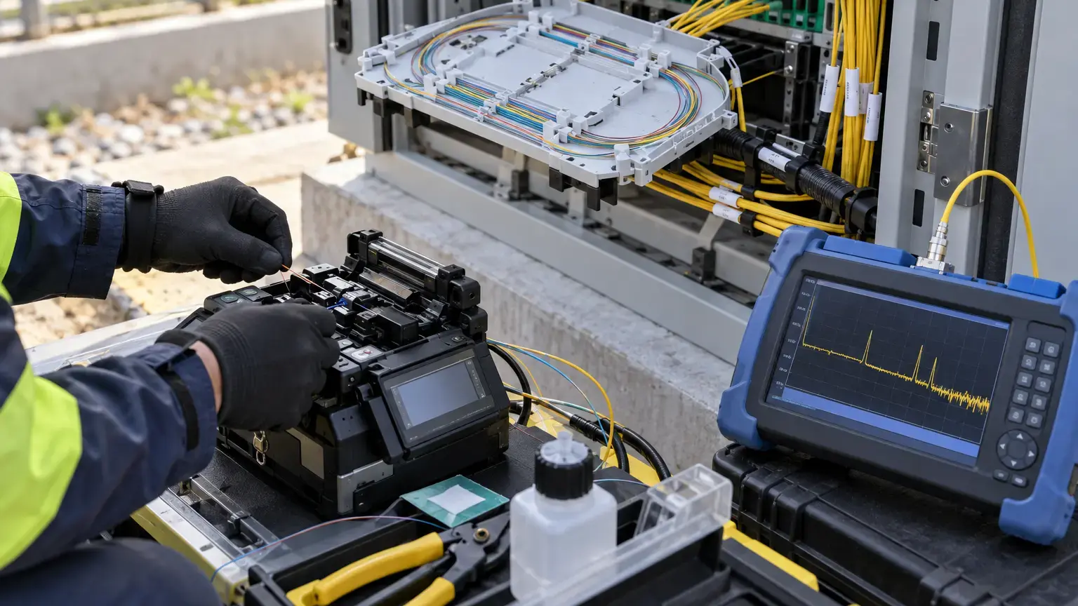
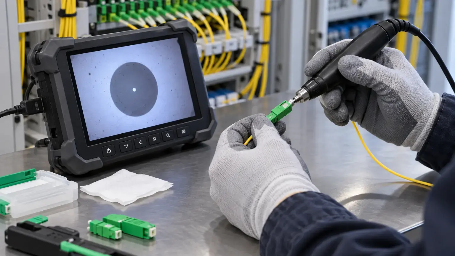
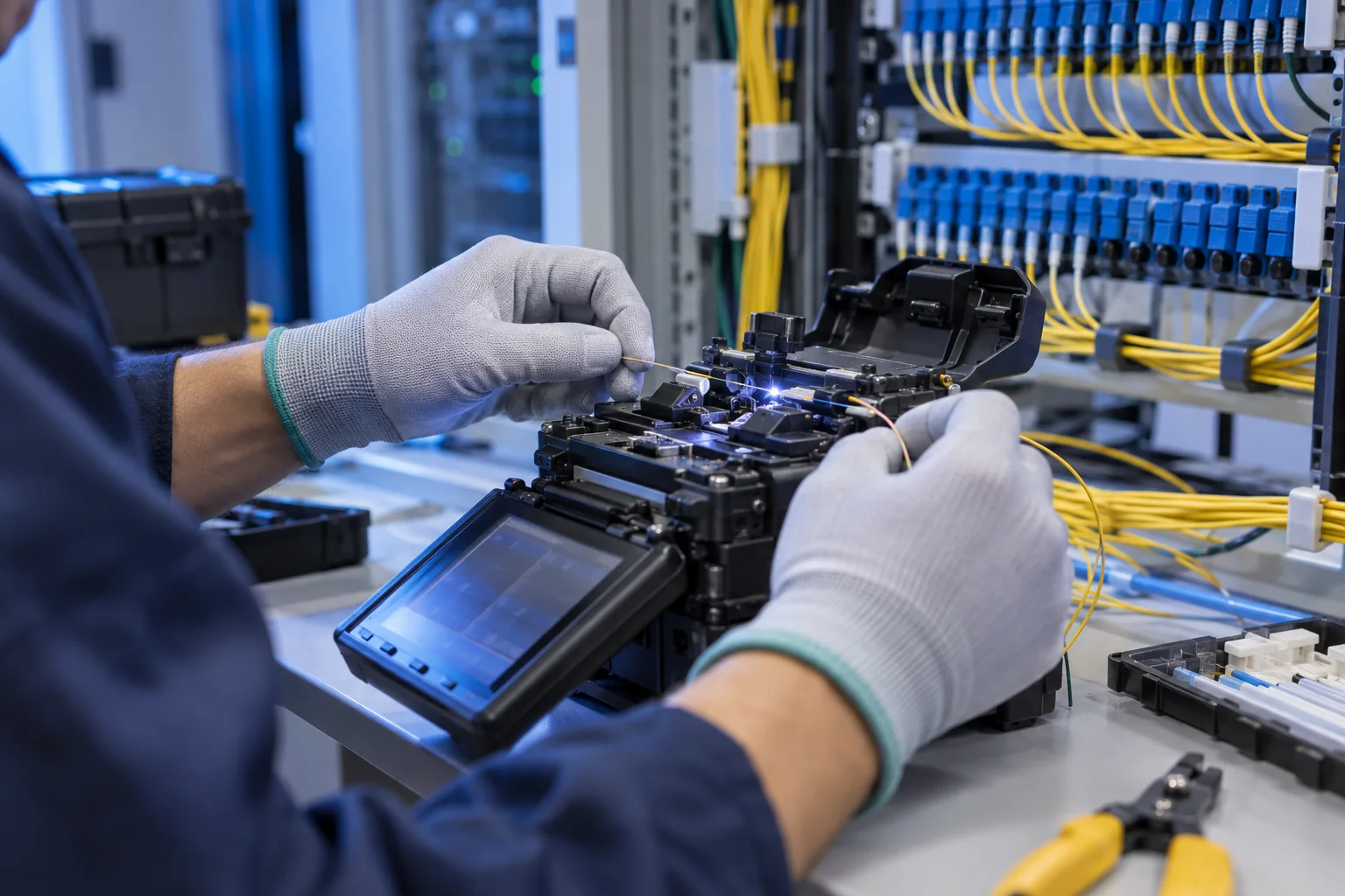
Why two directions change the answer
An OTDR estimates event loss from the change in backscatter before and after an event. When two fibers have different mode-field diameters or backscatter coefficients, a splice can appear to gain power in one direction and lose too much in the other. The fiber is not creating power. It is a measurement effect.
EXFO's technical note on OTDR gainers explains that this is common where G.652 standard singlemode fiber is joined to G.657 bend-insensitive fiber.
Bidirectional event loss = (A-to-B loss + B-to-A loss) ÷ 2.
Example: +0.42 dB and -0.18 dB average to 0.12 dB. Apply the project's acceptance limit to the average, while retaining both raw readings.
Use launch and receive cords
A strong reflection at the OTDR output temporarily overloads its receiver and creates a dead zone. A launch cord moves the first link connector beyond that zone. A receive cord provides fiber after the far-end connector so the instrument can measure it.
The FOA OTDR reference explains both functions. Corning's recommended test guidelines also call for a launch cable so the first event is visible. Select cord length from the event dead zone at the chosen pulse width, not from a universal rule.
Use cords compatible with the fiber under test. EXFO's OTDR and iOLM reference warns that a G.652 launch fiber used on G.657 can create an apparent gainer at the first connector and potentially hide high loss.
Freeze the test plan
Record cable and core IDs, endpoints, nominal length, fiber type, connector polish and wavelengths. Select the range, pulse width, averaging time, index of refraction, event thresholds and launch or receive compensation before production testing. Use the shortest pulse that still provides adequate dynamic range. A longer pulse reaches farther but widens dead zones and can merge nearby events.
Setup row: instrument and serial · calibration status · software version · wavelength · fiber type · launch cord ID and length · receive cord ID and length · range · pulse width · averaging time · IOR · thresholds · operator.
Keep interfaces stable
Inspect and clean the OTDR port, cords and link connectors before mating. Save files with cable, fiber, wavelength and direction. Fluke Networks' bidirectional testing guidance recommends leaving the launch and receive cords attached to the cabling under test and moving only the OTDR. This preserves connector alignment for the paired readings.
Match events by physical distance
Event 4 from end A may not be event 4 from end B. Pair events using route records and reversed position. For link length L, an event at distance d from end A should appear near L - d from end B, after compensation and measurement tolerance. If event locations do not match splice and route records, investigate before averaging.
Separate link loss from event diagnosis
An OTDR is valuable for event location and characterization, but it should not silently replace the agreed end-to-end loss method. FOA's installed cable-plant testing reference distinguishes insertion-loss testing from OTDR characterization. Define which result governs total link loss and which identifies event defects.
Stop acceptance when
- No launch cord hides the first connector in the dead zone.
- No receive cord prevents measurement of the last connector.
- Cord fiber type does not match the link.
- Only one direction exists for an apparent gainer.
- Different wavelengths, IOR values, pulse widths or thresholds are paired without explanation.
- The range ends before the receive cord or noise hides final events.
- Event locations conflict with the splice schedule.
- Raw traces are missing, ambiguous or reduced to screenshots.
Field acceptance worksheet
- Link, cable, core and endpoint IDs match drawings.
- Fiber type and connector polish are confirmed.
- Instrument calibration and software version are recorded.
- Launch and receive cords are identified, inspected and cleaned.
- Cord type is compatible and length exceeds the applicable dead zone.
- Wavelengths and settings follow the plan.
- The range includes the receive cord and noise floor.
- A-to-B and B-to-A raw traces are saved.
- Interfaces remain stable between direction tests.
- Events are paired by distance and records.
- Gainers and exaggerated losses are averaged.
- Unexpected events are investigated.
- Total loss and event limits are evaluated separately.
- Retests and corrective work remain traceable.
- Trace files, reports and as-built records are handed over together.
Minimum trace register
For every fiber and wavelength, retain both raw direction files, paired report, link length, cord IDs, settings, event table, averages, limits, operator, date, corrective-action reference and accepted revision. Link this register to the fiber core allocation worksheet, connector inspection worksheet and fiber testing acceptance guide.
Need a traceable OFC testing handover?
Share the route, fiber schedule, connector types, wavelengths and limits. We can align splicing, bidirectional OTDR records and as-built documentation around the site scope.
Discuss the fiber scope ↗