

OPTICAL FIBER INSTALLATION · 20 OCTOBER 2026
Fiber cable pulling and pathway readiness: a pre-installation worksheet
A fiber cable can pass its final optical test and still have been installed through a route that is difficult to maintain, unsafe to access or too close to its mechanical limits. Builders, property managers, LCOs, MSOs, ISPs and commercial facilities should approve the pathway and pulling method before the drum is opened. This worksheet turns that review into a traceable field record.
Visual reference photographs
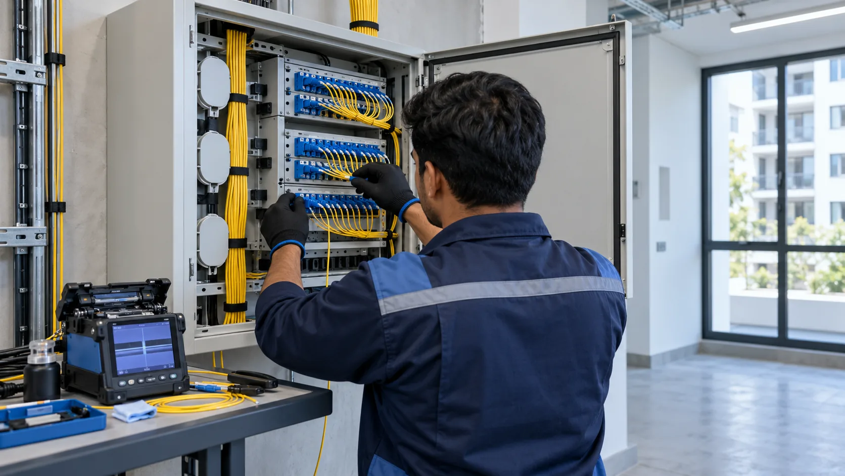

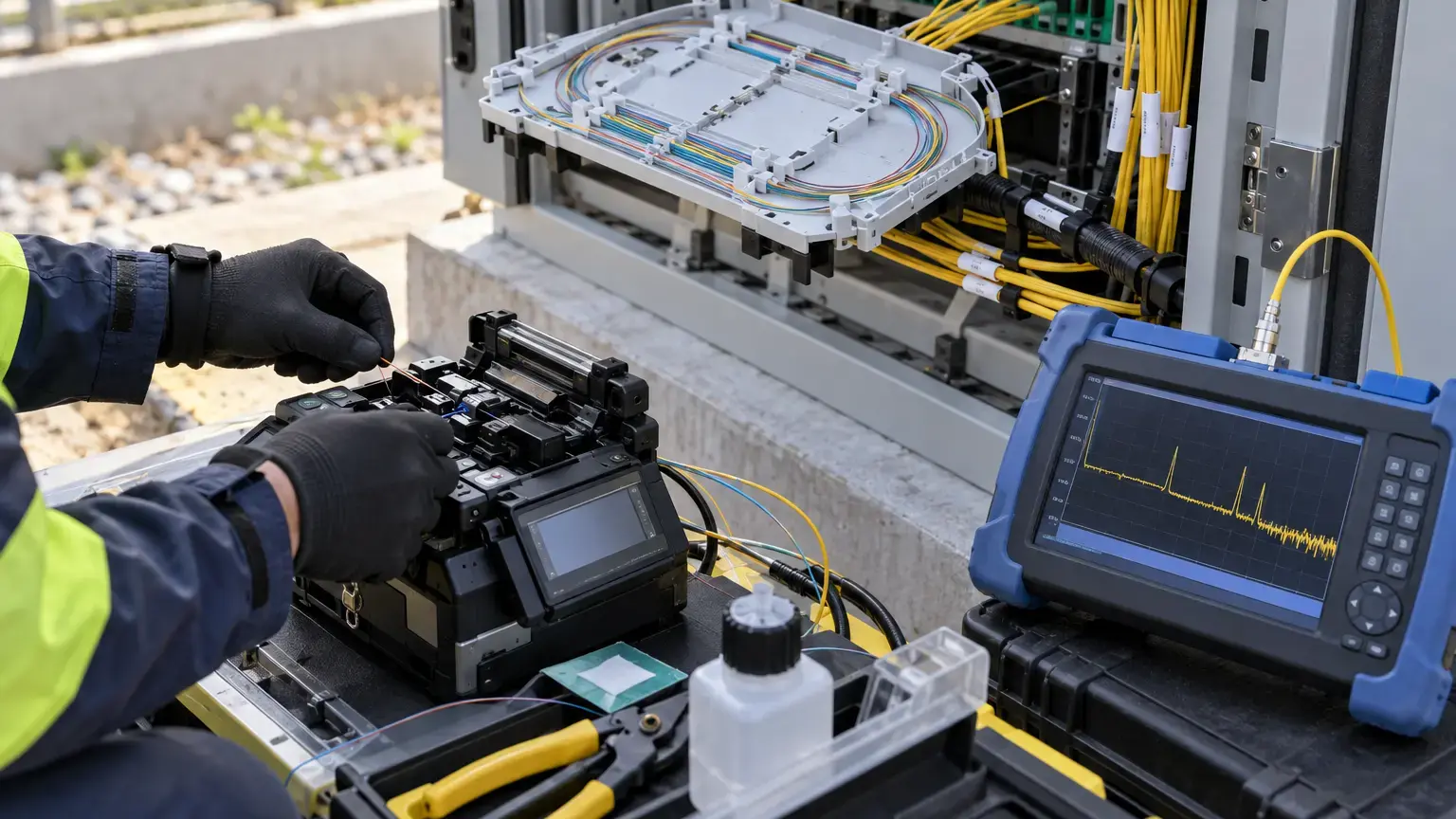
Approve the route before approving the pull
Start with a segment-by-segment route walk. Give every duct, tray, riser, chamber, pole transition, wall entry and equipment-room entry a stable identifier. Record the proposed cable type, drum length, start and end points, intermediate access points and intended splice locations. The drawing should show the path a crew can actually use, not only a straight line between two buildings.
Separate civil readiness from cable installation. A route is not ready merely because a duct exists. Confirm that the pathway is continuous, accessible, cleared, protected from sharp edges and provided with a usable draw rope or other approved installation method. Where the route shares space with other services, verify the approved separation, access and safety arrangements before work starts.
Route segment row: segment ID · start point · end point · pathway type · measured route length · access points · bends and transitions · draw-rope status · obstruction result · water or debris condition · responsible party · readiness status.
Use the selected cable specification, not a remembered rule
Every cable has mechanical limits that apply while it is being installed and after it is placed. Record the exact manufacturer, cable code, outside diameter, maximum installation tension, minimum loaded bend radius, minimum installed bend radius and applicable crush or sidewall limits. Keep the product data sheet and installation procedure with the work pack.
The Corning application note on pulling fiber cable in conduit tells installers to consider bend radius, tension, jamming and conduit fill before a pull. Corning's duct installation procedure also directs the crew to the specification sheet for the selected cable's allowed tension and loaded and installed bend radii. That cable-specific value governs the method.
The Fiber Optic Association bend-radius reference explains the widely used 20 times cable diameter under tension and 10 times cable diameter after installation guidance, while warning that some cables use different values. Treat those ratios as a cross-check only when the actual cable documentation supports them.
Check every bend as a loaded cable path
Mark each change of direction, duct mouth, chamber entry, riser turn and rack approach. A bend that looks acceptable after installation may be too tight while the cable is under pulling tension. Confirm that pulleys, sheaves, quadrants and guides are sized for the loaded condition and are placed so the cable cannot scrape an edge or jump out of the guide.
Do not confuse bend radius with bend diameter. Record which value the cable document specifies and which dimension the selected guide or sheave provides. Photograph critical transitions before and during the pull so the acceptance record shows the actual arrangement.
Critical-bend row: location ID · route drawing reference · cable outside diameter · manufacturer loaded limit · manufacturer installed limit · guide or bend-control method · verified dimension · photograph reference · accepted by.
Plan drum position, payoff and pulling direction
Choose the drum position by looking at the whole route. The best starting point may reduce severe bends, avoid pulling uphill through the longest section or place the drum where it can be handled safely. Record the drum ID, cable length, installation direction and the location of the pulling equipment. Confirm that the drum can rotate in the correct payoff direction without the cable dragging across the ground.
Define how tension will be applied and monitored, how the cable will be attached, whether a swivel or breakaway device is required and how communication will be maintained between the drum, intermediate access points and pulling end. The method statement should also define stop conditions for a blocked duct, unexpected tension, damaged jacket, jammed cable, failed communication or unsafe chamber condition.
Resolve ducts, chambers and building entries
Verify duct size and occupancy against the selected cable and installation method. A nominally empty duct may still contain silt, water, collapsed sections or undocumented cables. Prove continuity using the approved rodding, roping or proving method, and record the result for each segment. Any lubricant must be compatible with the cable jacket and pathway.
Chambers and handholes need enough space to guide the cable without violating bend limits. Confirm safe access, drainage condition, cover condition, cable support, entry sealing and the planned position of slack. At building entries, identify the transition between outside and inside cable requirements, firestopping responsibility, grounding or bonding requirements for cable elements where applicable, and the route to the final rack or splice enclosure.
Define slack and splice locations before cutting cable
Show each planned splice, termination and service loop on the route drawing. State the required usable slack at each location, the storage method and the minimum installed bend radius. Avoid leaving an unspecified coil in a chamber or rack. The handover record should show where the slack is stored, how much was left and which cable segment it belongs to.
Check that splice closures, panels and racks are accessible after the building or external works are complete. A technically correct splice point is still a poor operational choice if it will sit behind a finished wall, beneath standing water or inside an uncontrolled electrical space.
Witness the pull and record exceptions
Before starting, hold a short readiness review with the installation team. Confirm the route, cable drum, specification limits, equipment, roles, communications and stop conditions. During the pull, record the start and finish times, observed maximum tension when a suitable measuring method is part of the approved plan, intermediate checks, lubricant used, cable-meter marks and any event that stopped or changed the work.
After placement, inspect the accessible jacket, entries, supports, service loops and termination approaches. Record damage, unexpected route changes, exceeded limits or missing photographs as exceptions. Do not hide a suspected over-tension or bend event behind a passing power-meter result. The responsible engineer should decide whether additional inspection, testing or cable replacement is required.
The free NECA/FOA 301 installation standard connects installation practices with testing and documentation. Use it with the cable manufacturer's current instructions and the project specification rather than treating any single generic checklist as the complete method.
Pre-installation readiness worksheet
- The cable manufacturer, exact product code and drum ID are recorded.
- The latest cable data sheet and installation procedure are attached.
- Loaded and installed bend limits are written into the work pack.
- Maximum installation tension and the approved monitoring method are defined.
- Every route segment has a stable identifier and measured length.
- Duct continuity, occupancy, draw rope and cleanliness are verified.
- Chambers, handholes and risers are safe, accessible and ready.
- Every critical bend and transition has an approved guide arrangement.
- Drum position, payoff direction and pulling direction are agreed.
- The pulling attachment, swivel and breakaway arrangement are approved where required.
- Compatible lubricant and application responsibility are documented where used.
- Pulling crew roles, communications and stop conditions are understood.
- Building entries, sealing, firestopping and internal route ownership are assigned.
- Splice points, termination points and slack-storage locations are shown.
- Photograph, meter-mark and exception records are prepared before work starts.
Minimum installation and handover record
Retain the approved route drawing, route-readiness register, cable and drum details, product data sheet, installation method, bend and tension limits, equipment list, pulling log, cable-meter marks, critical-stage photographs, installed slack record, splice and termination schedule, test-file references, exception register and acceptance signatures. Connect the final route to the fiber core allocation and route-records worksheet and the fiber testing acceptance record.
Preparing an OFC backbone or building fiber route?
Share the site plan, pathway layout, cable schedule, termination locations and project sequence. We can review route readiness, fiber installation, splicing, testing and handover requirements around the actual scope.
Discuss the fiber route ↗